Help
Calibration
Calibration Overview
First Calibration
The first calibration during a new setup is the most difficult. It usually requires adjusting the physical position of the flash units. It is HIGHLY RECOMMENDED that you work with us for your first calibration.
After the initial setup, calibration is relatively straightforward. Particularly if you only have a single calibration.
Calibrating for a Single Thickness
A single calibration is recommended as it requires less time and effort to calibrate your photostation. When using a single calibration you should calibrate based on your thickess material (typically 3cm). To maintain dimensional accuracy when photographing thinner material, you place spacers behind the material to bring the face of the material to 3cm.
The spacer can be nothing more than wooden sticks of the correct thickness.
To photograph a 2cm slab with a 3cm calibration, place 1cm sticks behind the slab. To photograph 1cm material with a 3cm calibration, place a 2cm spacer behind the slab.
Calibrating for Many Material Thickness
While it is not recommended, Slabsmith supports a calibration for each material thickness. The process is more involved and takes more time. To create multiple calibrations, you need to first validate the photostation with the calibration targets flat against the A-frame, then you need to set up and calibrate for each needed thickness.
Calibrating Your Photostation
NOTE: The instructions below are for calibrating a single material thickness. While not recommended, if you require multiple calibrations, please contact us for the differences in the proceedure.
Setting up for a single calibration
1- Place your calibration targets on the A-frame. First place your foam for the correct thickness on the A-frame, then place the calibration targets in front of the foam. Make sure the calibration targets are flat and tight together. You can use painters tape to help hold them together, just be sure to keep the tape at least 1/2″ (1cm) from any of the black dots on the calibration targets.
a) Open the Calibration module from Slabsmith’s home tab.
b) Make sure you are in good focus. Set the camera to ‘Auto Focus’, take one picture, then set it back to manual focus if your picture is not clear.
c) Set all 4 flashes to full power. This is done using the slider on the back of Alien Bee lights, the slider should be all the way to the side of the flash with the red test button.
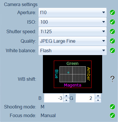
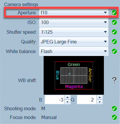
d) Set the initial camera settings as follows:
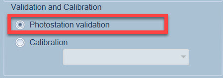
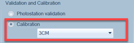
e) Be sure that “Photostation validation” is selected.
Validation requires two validation targets to be mounted on the A-frame, under the slab and always visible while photographing slabs. This help document assumes you are using validation targets when calibrating.
2- Take a picture.
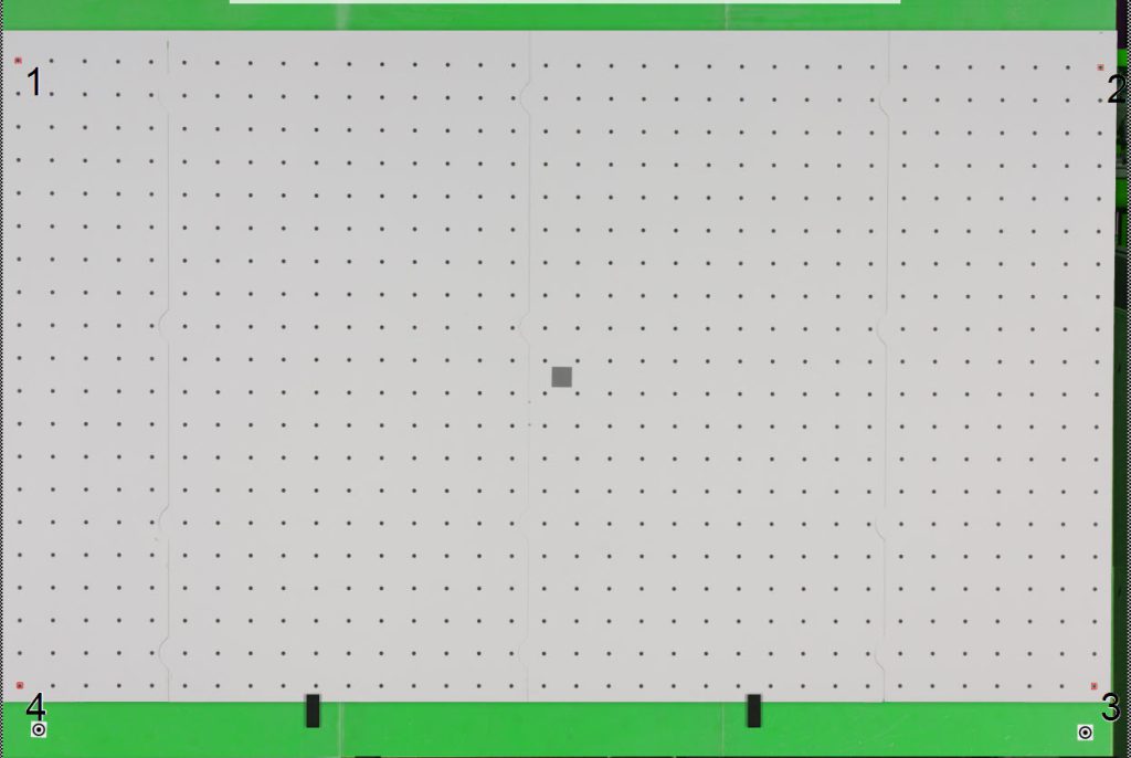
a) Click the Camera button. Slabsmith will automatically find the 4 dots in the corners. Calibration requires the same number of dots in each row and column. If there is any trouble, you can click on a point close to the correct dots to move the selected dots. When correct it should look similar to this:
b) Click the green “GO” button. This starts the calibration process.
c) Click “OK” to the validation target message. When complete, a message will pop up to tell you that the validation targets where found. If both targets where not found you may need to replace the targets with new validation targets. ( The validation targets are the 2″ bullseyes at the bottom of the A-frame in the picture above)
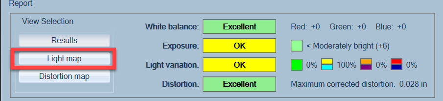
The Calibration Report
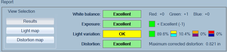
The calibration report provides the information needed to adjust the camera and lights to get accurate and consistent colors. Dimensional accuracy is never a problem if your calibration targets are flat and tight together.
Follow the steps below to adjust your camera and lights for accurate lighting.
Adusting for the White balance and Exposure.
A perfect White Balance and Exposure both have values of “0”. In practive +/-1 point is acceptable.
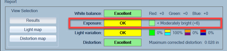
1) Adjusting the “Exposure”. The initial exposure will probably not be near to “0”. Positive numbers are too bright, negative numbers are too dark.
Large exposure adjustments are made by changing the “Aperture” setting on the camera.
a) Exposure too dark (negative number). Change the Aperture F-stop to a smaller number. Try F9, or F8. Then take another picture to see the results of the change in the Exposure numbers.
b) Exposure too bright (positive number). Change the Aperture F-stop to a larger number. Try F11, F13, etc. Then take another picture to see the results of the change in the Exposure numbers.
As you adjust the Aperture, you will find that one setting will be too bright, and the next setting will be too dark. Leave the aperture on the setting that is too bright, the balance of the exposure adjustment will be done by changing the power on the flashes.
In this example the exposure finished at +6 before adjusting the flashes.
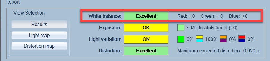
2) Adjusting the “White Balance”. A perfect white balance is (Red: 0 Green: 0 Blue: 0). In practive +/- one is acceptable.
The white balance should already be close to 0,0,0 with starting numbers set to -3,+2 as in the image below.
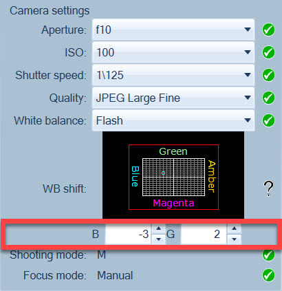
In the image above you will see a blue dot on the color space grid. It is surrounded by 4 colors (Blue,Green,Magenta,Amber).
Move the dot with the numbers below the grid to adjust the white balance to near zero for all three computer colors (RGB) that are listed in the report at the top of your screen. You can mostly ignore the Amber and just think of Magenta=Red, Blue=Blue, and Green=Green.
You will find that shifting for one color may slightly affect the other colors, so you may need to play a little bit.
3) Adjusting the flashes
The final lighting adjustments are made by looking at the “Light map”. Select the “Light map” button to see the light map.
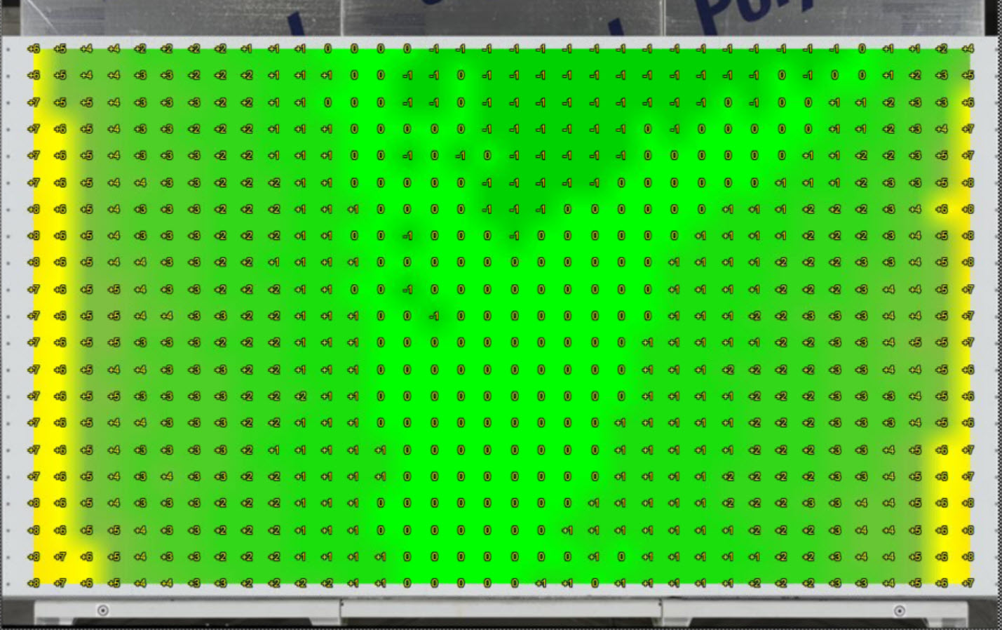
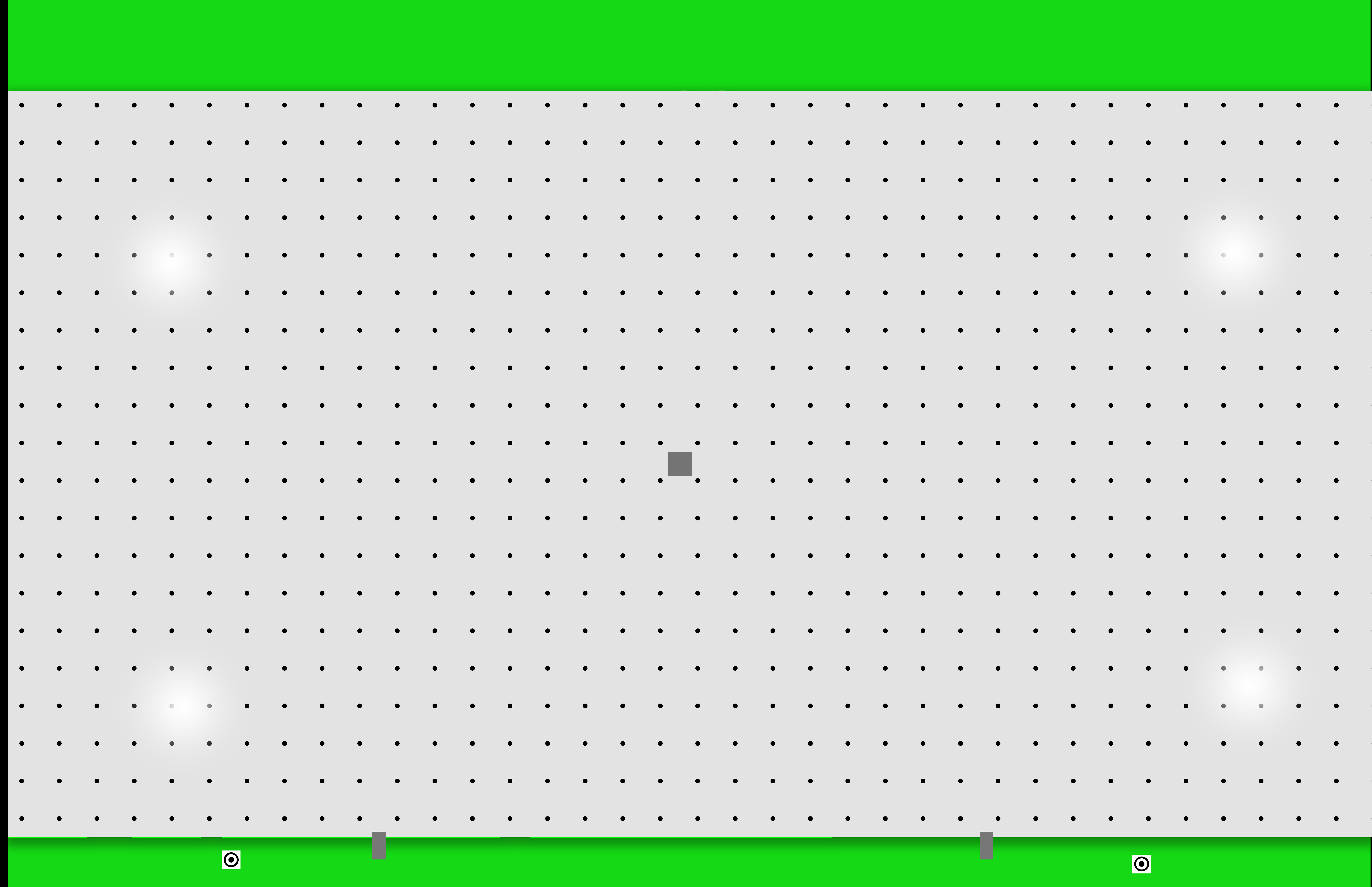
The light map is color coded to show how the light varies across the A-frame. Green represents a low lighting variation which is what is needed for accurate and consistent colors. The light map will look similar to the image below:
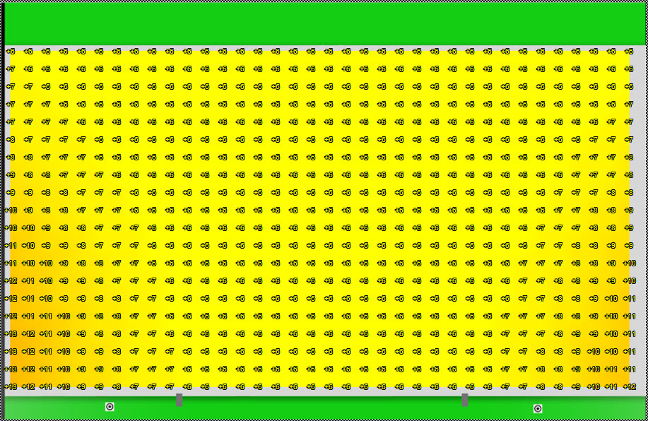
In the light map above everything is bright because the exposure is at +6. However you can see the two bottom corners are a little bit brighter at around +12 and +13.
The goal is to have the entire area Green and the Exposure within about 1 point of 0.
The exposure is based on the gray card in the middle of the calibration targets, and you will see that the numbers in the middle of the targets is at +6. To get everything green, there needs to be a maximum varation from 0 at the gray card of no more that +5/-5 points.
Even though everything is bright before adjusting the lights, our total variation is very good, ranging from a minimum of +6 to a maximum of +13. Well withing the limits.
Adusting the flash power down
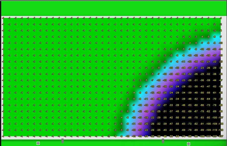
Start by adjusting ONLY the bottom lights about 1/8 of an inch down from full power. Then take another picture, look at the exposure number which will be lower, then look at the light map. It will look similar to this (exposure was down to +2 after adjusting the lights):
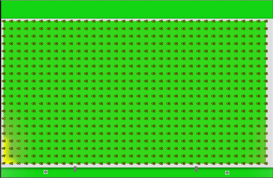
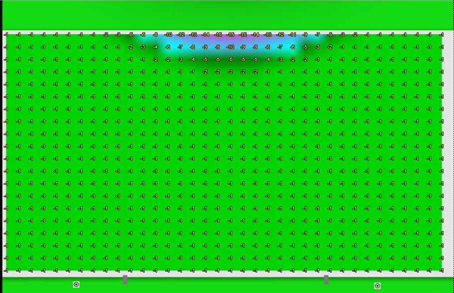
At this point the lower left has a little more light then the lower right, so now adjust ONLY the left side flash down in power. When everything is good, the entire area will be green. In the example below, the exposure was down to -1. This is good. -1, 0, or +1 are all acceptable as the final exposure.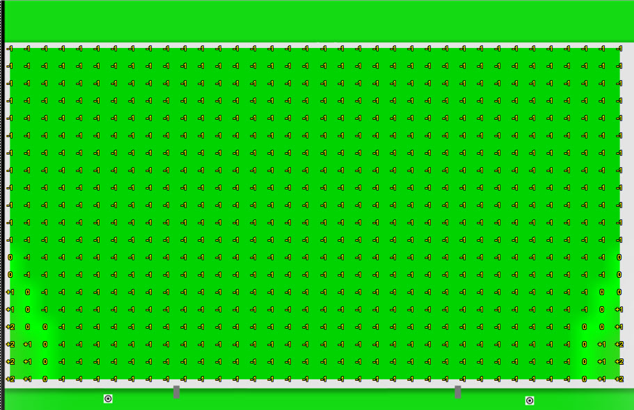
You probably will not have this low of variation, but if everywhere you could photograph a slab is green, then it’s a good calibration.
Finding the center point of the Exposure
When you think everything is good, take a series of pictures while taking note of the exposure. You will see that the exposure over multiple pictures will vary by +1/-1 from it’s centerpoint. In other words, there is a small variation in the lights from one picture to another.
By taking multiple pictures, you will find the center of the varation. The center of the variation should be -1,0 or +1 when you are ready to save the validation. If it’s not, you will need to continue to make slight adjustments on the flash power.
Saving the validation
When you do have the determined the centerpoint of the flash variation, keep taking pictures until the exposure is on the centerpoint. Then click the “Save” button to save the validation.
It notify you that you will need to do a calibration if you save the validation. Click “OK”.
The first step of the calibration proceedure (validation) will be complete. The next step is to perform the calibration and to set the 0,0 point of the A-frame.
4) Completing the Calibration
After saving the validation, select “Calibration”.
This step is completed in exactly the same way as the validation, with the addition of setting the 0,0 point of the A-frame.
1- Click the “Camera” button to take a picture of the calibration targets. Be sure that the 4 corners of the calibration area are selected correctly.
2- Click the green “Go” button to start the calibration process. Repeat this process until the Exposure is the same as the midpoint you saved during Validation. ( -1, 0 or +1)
3- Set the origin by dragging the crosshair in the middle of the screen to the 0,0 point on the A-frame that matches the 0,0 point on the saw. (See “Setting the ORigin” below for a detailed description.)
4- Click the “Save” button to complete the calibration process.
Note: It’s alway a good idea to close the Calibration module, then open Slab Maker and take a picture to make sure everything is correct before removing your Calibration targets from the A-Frame.
Setting the Origin (the details)
How you set the A-Frame origin (0,0 poing) depends on how you will be aligning your slab with your saw. The most common methods are detailed below.
1- Using fixed points. In this method the A-frame is constructed with slab rests that match the slab rests on the saw.
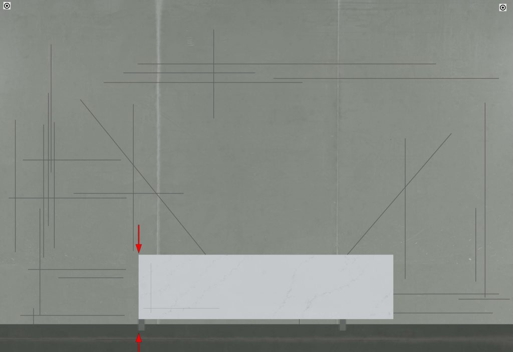
The easiest way to set the origin to match the saw is to first place the crosshairs on a common point that matches on both the A-frame and your saw. One of the slab rests is usually a good place. (see arrow below)
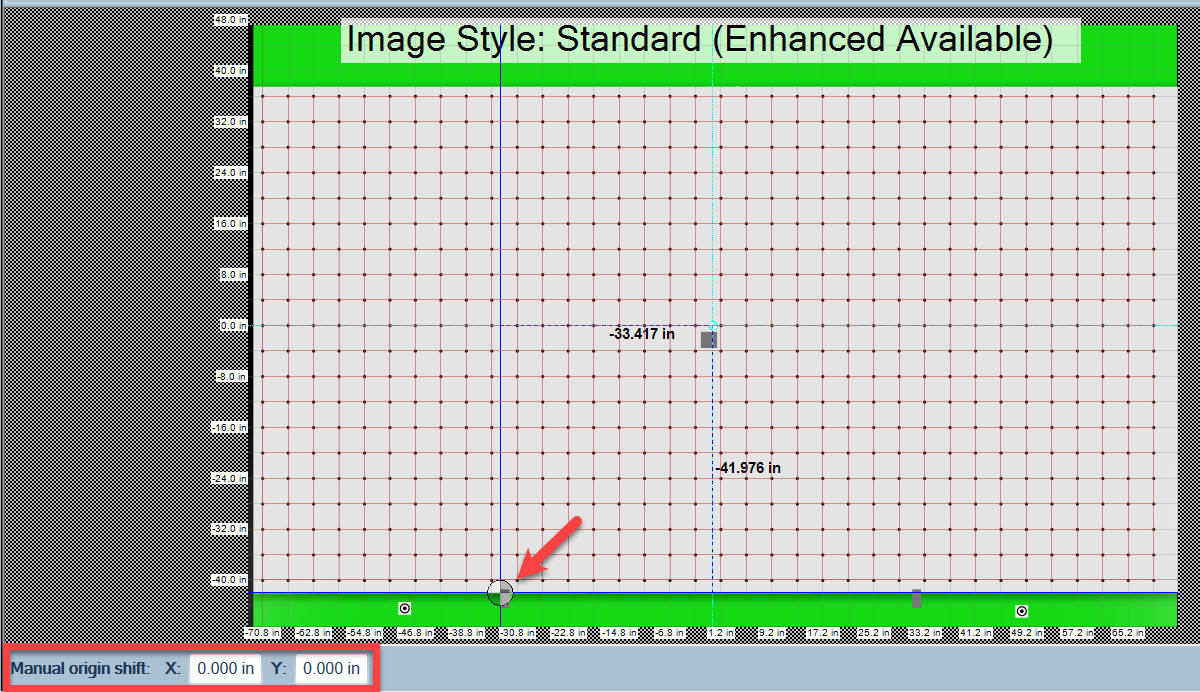
After placing the crosshairs on the slab rest, go to your saw and measure the distance from the slab rest to the 0,0 point on your saw.
Then using the manual origin shift (red box above) type the distance into the X (usually a negative value) and select the {Tab} key to apply the shift. If you need to shift the Y value, repeat the proceedure in the Y.
This will place the origin close but not perfectly. For the best accuracy, follow the instructions for “Adjusting the 0,0 Point” to precisely place the origin by making a test cut.
2- Using a Camera or Laser to align the slab on your saw.
If your saw uses a camera or a laser projector to align the slab on the saw, place the crosshairs anywhere near the lower left corner of the calibration targets on your screen.
Adjusting the 0,0 point
Note: This help section provides instructions for making the final adjustments to the 0,0 position of your photostations A-frame. This only applies when you are using physical slab rests to locate the slab on your saw. If your saw uses a camera, or projection laser to locate the position of the slab, this faq does not apply to you.
Background
When a Slabsmith™ photostation is calibrated the last step in the process is to set the 0,0 position of the A-frame to match the 0,0 position of the saw. This is done visually by dragging the zero point from the center of the graphics screen to the approximate position that matches the saw’s 0,0 position.
Because this is only an approximate position, after saving the calibration you will need to follow the proceedure documented here to adjust the calibration to precisely match the saw.
What you need
1- A piece of scrap material with a clean 90 degree corner on the lower left. The left edge and bottom edge must be flat.
2- A straight edge
3- A pencil or marker to draw narrow, but easily visible lines on the scrap material.
4- A DXF file of a 12″(300mm) square.
5- A Tape Measure
Instructions
Step 1- Prepare the scrap material
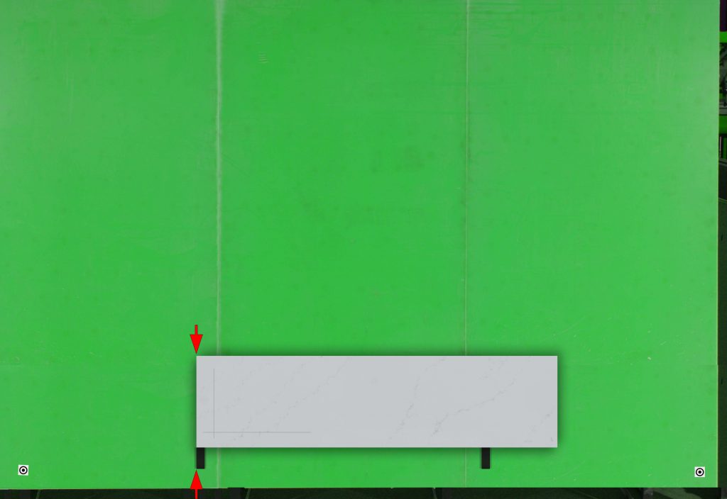
Locate a piece of scrap material that has a clean 90 degree corner on the lower left. Using a straight edge, make a line parallel to the left edge, and a second line parallel with the bottom edge.
These lines do not have to be any specific distance from the edge.
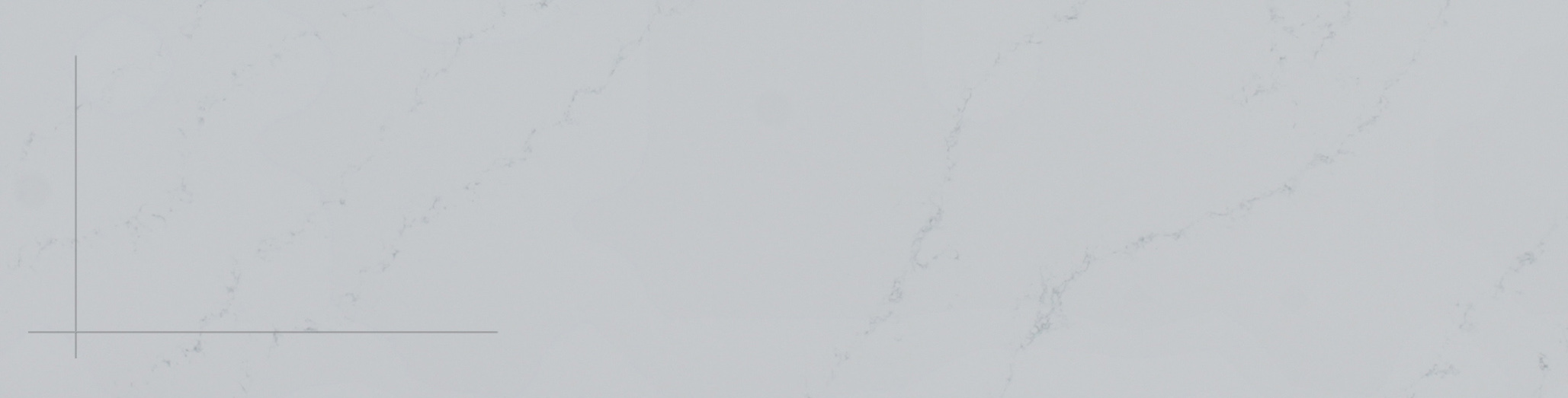 Scrap material with parallel lines
Step 2- Place the scrap material on the A-frame
Place the material on the photostation A-frame and align the left edge of the material with the left of of the slab rest.
Step 3- Create a temporary digital slab
Open the Slab Maker Module and create a digital slab. When the suggested inventory ID is displayed, change it to something easy to find like “AATest”. There isn’t any need to fill out the slab properties. This is a temporary slab and you can delete it from the database after completing the 0,0 procedure.
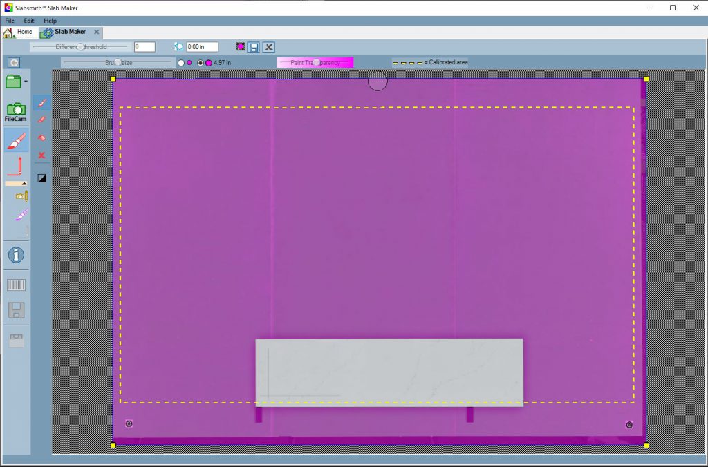 Take a photo of the scrap
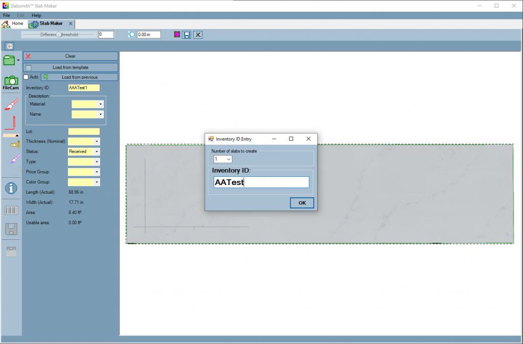 Replace inventory ID with an easy to remember name
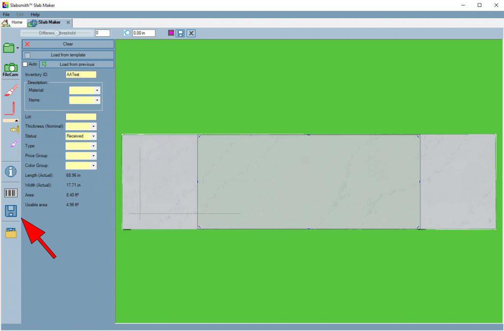 Save the temporary slab
Step 4- Open Perfect Match™ and load the files
Open Perfect Match™ IMPORTANT: If Perfect Match is already open, close it and re-open it.
After opening Perfect Match™, open the DXF file containing the square, and load the temporary digital slab you just saved.
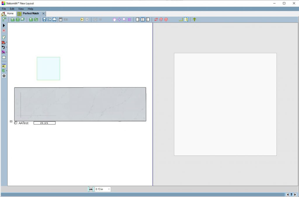 The Temporary Slab and the square
Step 5- Place the square on the lines
Move the square over the lines that you drew on the scrap material so that the lower left corner of the square is at the intersection of the two lines.
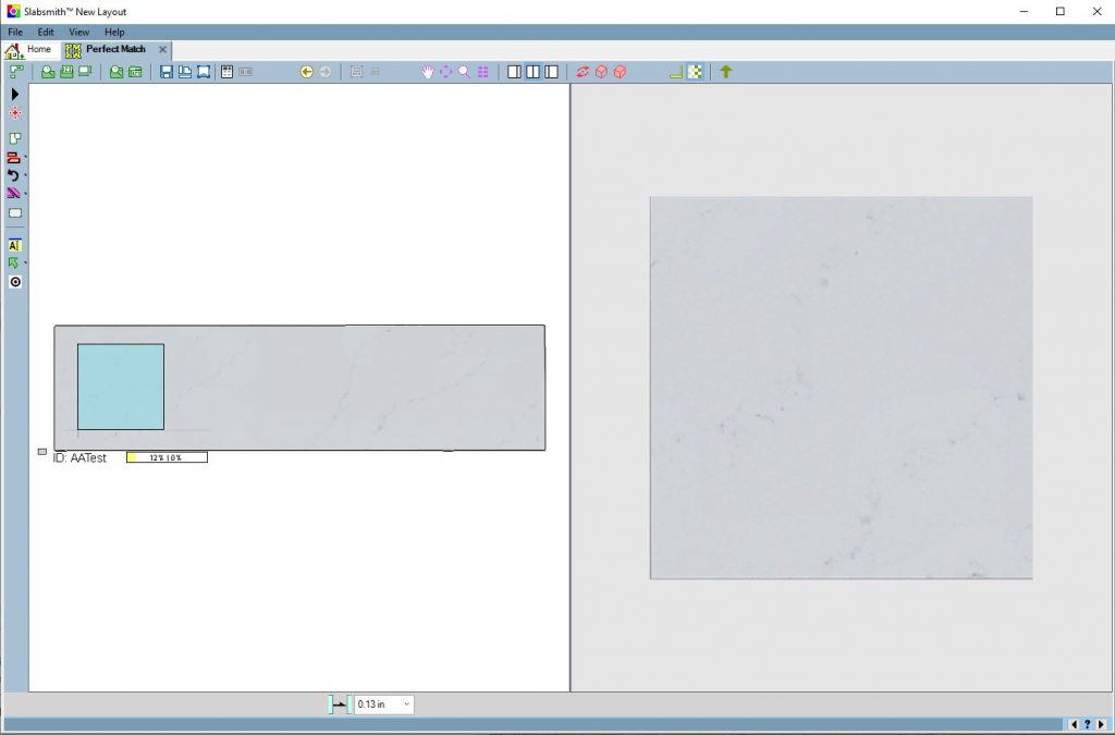 Move the square over the lines
Zoom into the corner and accurately place the Square in the center of the two lines.
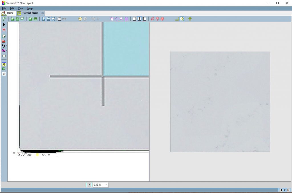 Accurately place the corner of the square in the center of the lines
Step 6 – Export the layout as a DXF file
Export the layout as a DXF file using the toolbar button or “File | Export | DXF”
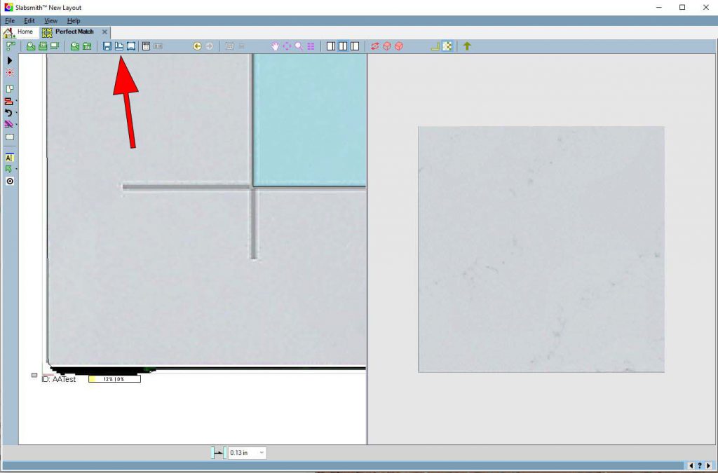 Export layout as a dxf file
Step 7 – Program the saw
Open the DXF layout file from step 6 in your Saw’s programming software.
Create a path for the left side and bottom side of the square.
Step 8 – Place the scrap material on the saw and cut it
Place the scrap material on the saw aligning it with the matching slab rest.
 Place the scrap on the saw aligned with the slab rest
After placing the scrap on the saw, run the program to cut the two lines.
IMPORTANT: DO NOT REMOVE THE MATERIAL FROM THE SAW. You will need to recut the material in a few minutes as a check after you adjust the origin.
Step 9- Measure the distance from the cut to each of the lines
After cutting the two lines, measure the distance from the saw cut, to the lines that you drew.
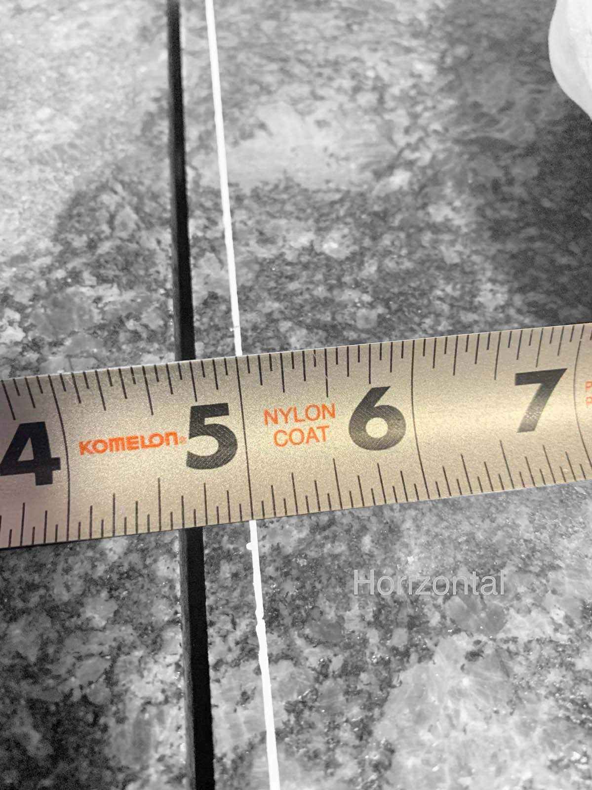
The vertical line corresponds to the “X” axis, and the horizontal line corresponds to the “Y” axis. Write down the values: X=? and Y=?.
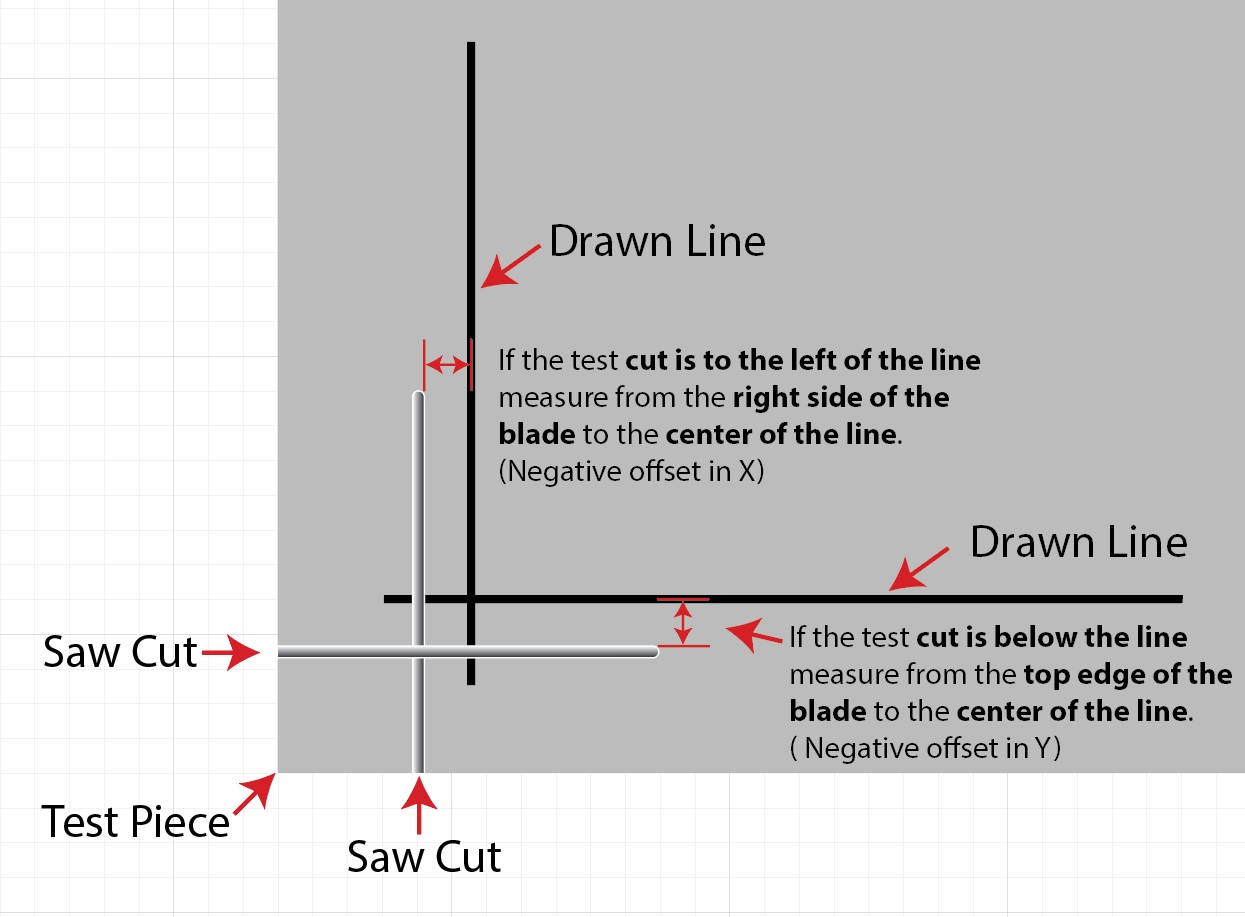
If the saw cut to the left of the line.
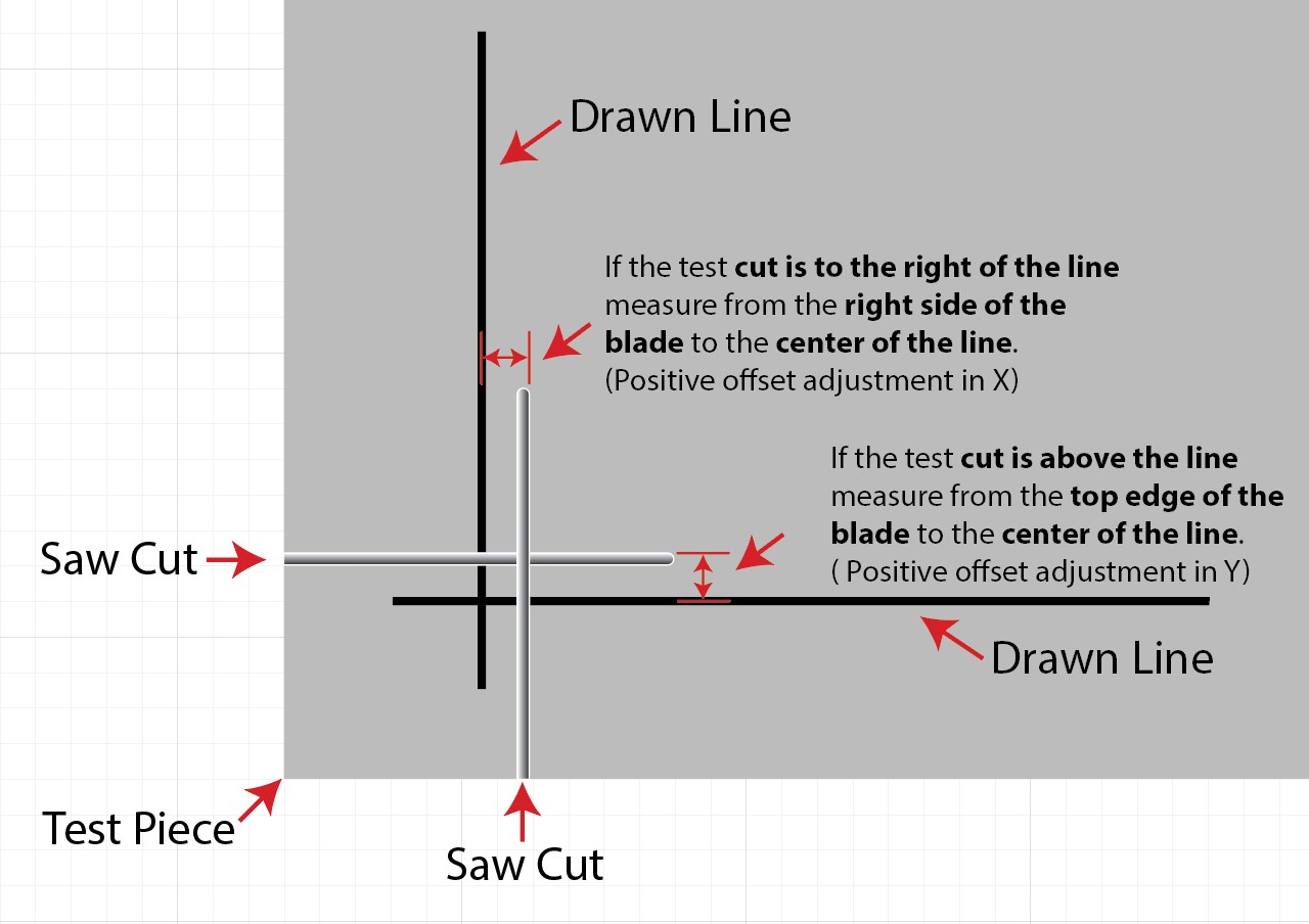
If the saw cut to the right of the line.
When the zero is correct.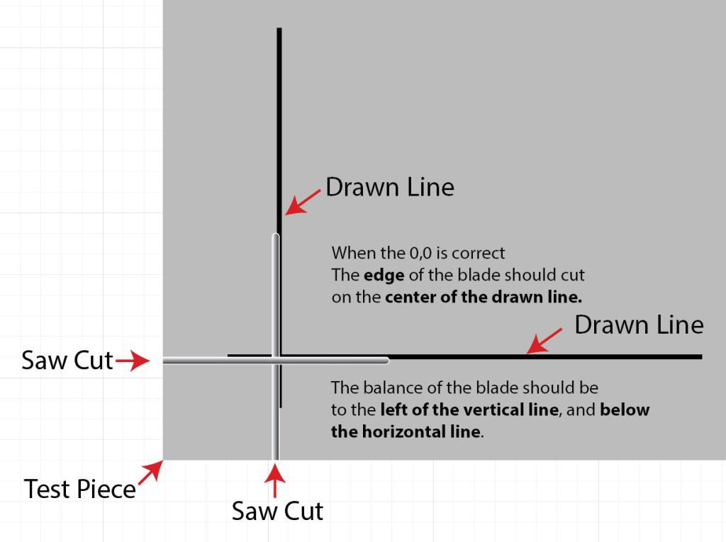
Step 10 – Adjust the calibration 0,0
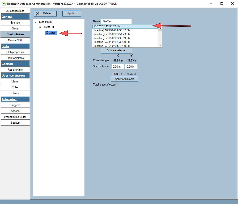
Open the Slabsmith™ Database Administration program. If you don’t have it on your computer, it will always be accesible on the computer that hosts the Slabsmith Database.
-
- Select the “Photostation” Tab
- Open the tree until you can see your calibration. If you only have one calibration, it should look like the image below.
- (you may have more than one calibration, for instance one for 2cm and one for 3cm, if you do this process must be completed for each calibration individually)
- Select the top calibration on the right side
 Select the calibration
Step 11 – Enter the X and Y shift distance
These are the numbers that you wrote down at the saw. The distance from the saw cut to the middle of the line your drew.
X-Shift instructions (line on the left of the scrap):
If the saw needs to move to the right (+) to reach the line, you will enter a negative number in the X position of the shift distance.
If the the saw needs to move to the left (-) to reach the line, you will enter a positive number in the X position of the shift distance.
Y-Shift instructions (line on the bottom of the scrap):
If the saw needs to move up (+) to reach the line, you will enter a negative number in the Y position of the shift distance.
If the the saw needs to move down (-) to reach the line, you will enter a positive number in the Y position of the shift distance.
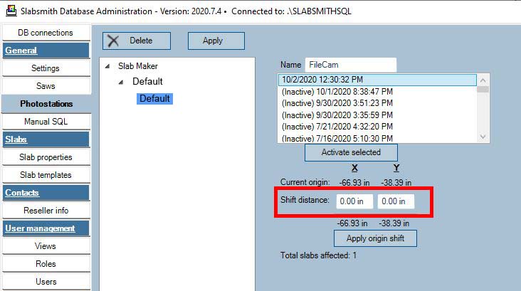 Area to enter the zero shift values.
When you enter the number in either, select the {Tab} key to see the result below the entry box. When you are satisfied that you have both numbers entered correctly, select the “Apply origin shift” button to update the calibration with the new zero position.
Note: This updates the origin on any existing digital slabs created with this calibration. It will not affect slabs that were created with previous calibrations.
Step 12 – Repeat steps 4 – 9
Repeat steps 4 thru 8 to verify that you have correctly adjusted the zero and that the saw is cutting down the center of the line. If the saw is cutting the line, you have completed the calibration zero process.
If you find that you are twice as far from the line as your first try, you probably entered a positive number in the shift when you needed a negative number or a negative number when you needed a postive number. If this happened, continue with step 9, reverse the sign and double the shift distance to correct this.
Troubleshooting
Common issues
1- Bright Edges on the Light Map
If your calibration is otherwise good, but you still have bright edges on the light map it’s an indication that your lights need to be wider.
2- Lights in the picture
The flashes are MUCH to narrow. In this case you are actually seeing the lights in the picture. The lights need to be moved MUCH wider.
3- Flash not working
If a flash doesn’t fire, the light map will be very dark on the corner of that flash that is not working. In the image above, the lower right light did not fire.
4- Dark top center
When the light map has a dark band on the top it could be one of the following:
a) The top flashes need to be higher
b) The top lights are not on full power. In most cases the top lights should always be on full power with all adjustments done to only the bottom two lights.