Support
Photostation Planning
Determining the space and placement of the Slabsmith™ photostation
Photostation Layout Essentials
The correct positioning of the camera, lights and A-frame will produced consistent and repeatable digital slabs of accurate dimension and color.
The flash units are usually the difficult part of finding the space for the photostation. The flashes are critical to accurate and repeatable colors, and there are no shortcuts to good lighting position.
The camera and the A-frame must be permanently secured in place. It is also preferable to permanently fix the lights in place, but if absolutely necessary, the lights can be moved into position to take photos and placed out of the way, when not needed.
If it is necessary to move the lights, it is highly recommended that you implement the ‘Validation’ function when calibrating the photostation. The validation will warn the user if the lighting significantly changes from the time of calibration.
Note: Finding the best space and workflow for a photostation can be a challenge. We can help. Call us!
Note 2: If you have very little space, you may want to consider a horizontal table.
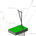
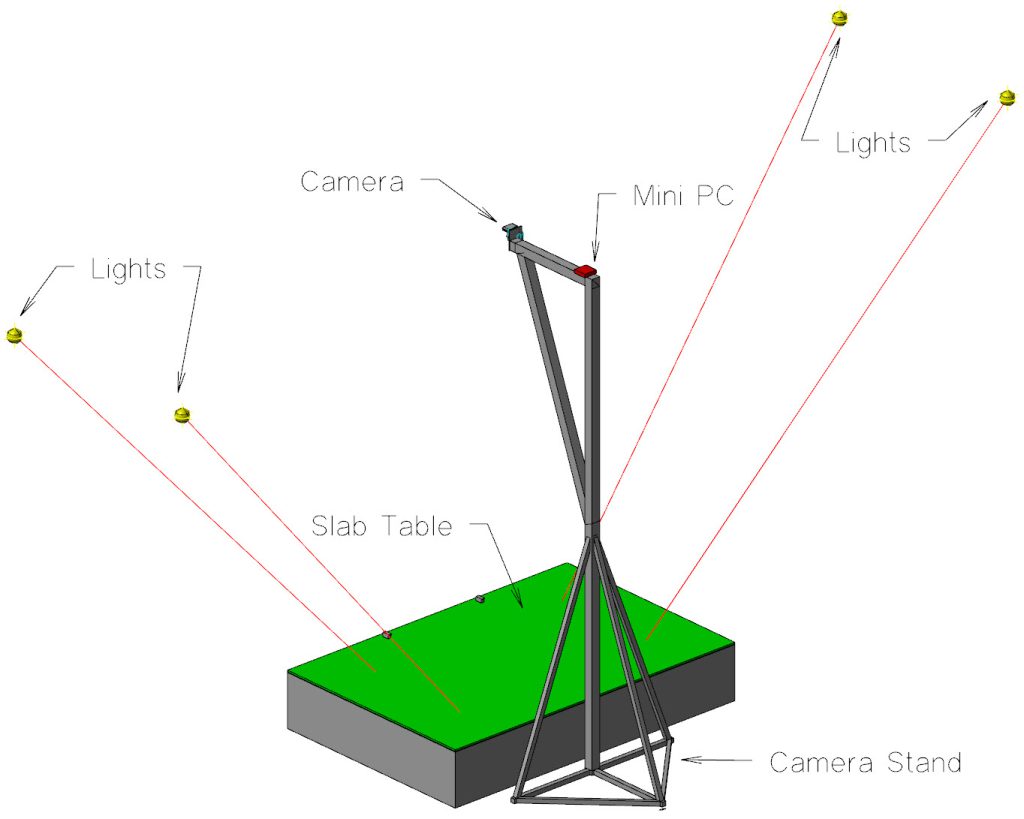
Photostation Layout – 3D View
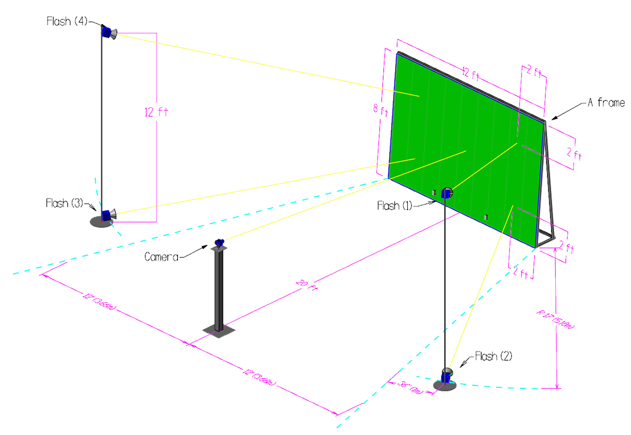
Layout details for Photostations using a zoom lens
First complete the following measurements. (see the diagram above for reference).
- Determine the position of the camera and A-frame.
- While the drawing above and below shows “20ft’, this is only a sample distance.
- With the standard 18mm – 55mm zoom lens the camera distance can be between 10ft and 29.5ft (>20ft recommended)
- We recommend 20+ft, to avoid needing more than one calibration for different material thicknesses.
- At the camera, measure to the right and parallel to the A-frame, the width of the A-frame. (Typically 12′ / 3.6m).
- From that point, strike a line to the right front corner of the A-frame.
- Offset this line 3′ / 1m to the right.
- Strike a 17′ / 5.1m arc across the offset line from the corner of the A-frame.
The point where the arc intersects the offset line is the starting point for the flash stand. Your flash stand will not be any closer to the A-frame than this point, but it may need to be wider and further from the A-frame. This is simply the starting point when doing the first calibration, BEFORE the light stands are bolted to the floor. They may need to be moved slightly during the initial calibration.
Repeat this procedure on the left side of the photostation to find the initial position of the second flash stand.
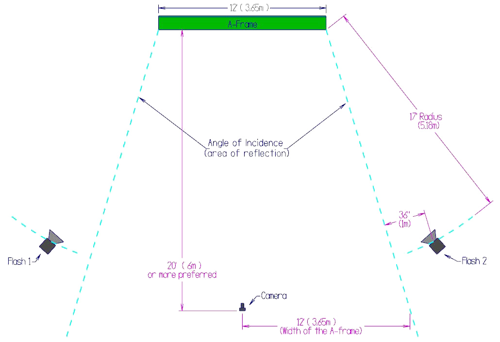
Sample Photostation Layout Plan View for a Zoom Lens
Layout details for Photostations using a prime lens
Prime lens – Prime lenses are lenses with a fixed focal length (they don’t zoom). This means less “glass” in the lens, resulting in sharper, higher-contrast images. The downside is slightly harder and restricted setup of the photostation. Since the lens does not zoom, the camera must be place at a specific distance from the photostation A-frame. If you are willing to spend a little more time and effort on the initial setup, using a prime lens will improve your pictures forever.
The following drawings provide rough dimensions for a Slabsmith™ photostation using a variety of prime lenses.
Please keep in mind that these are MINIMUM dimensions. You may need to slightly adjust the camera position and light position a little further away than the plans call for. The final positions of the camera and lights cannot not be detrimined until the first calibration of the photostation.
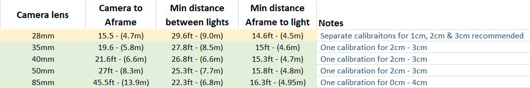
Distance Grid
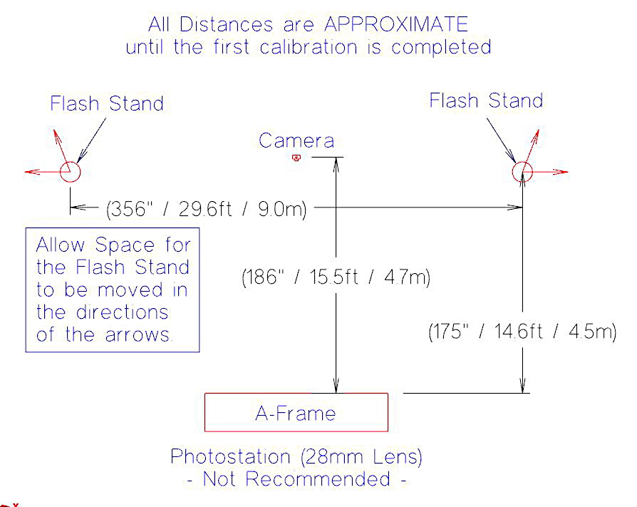
Photostation (28mm Lens)
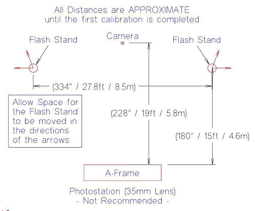
Photostation (35mm Lens)
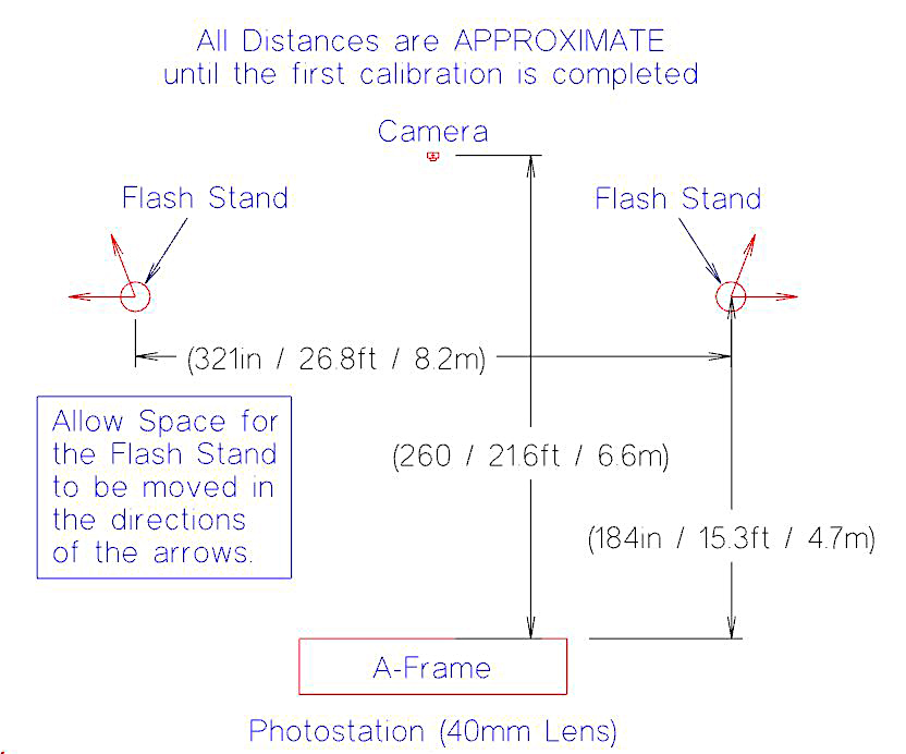
Photostation (40mm Lens)
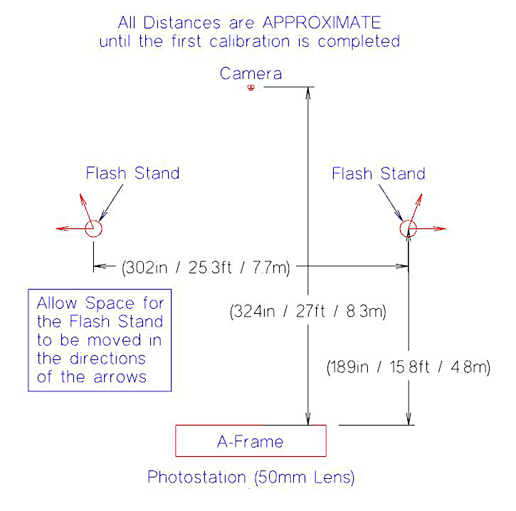
Photostation (50mm Lens)
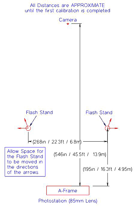
Photostation (85mm Lens)
Additional considerations for the photostation
There are many factors that must be considered when planning where you will set up your photo station. Your work flow, ambient light changes (ie- garage doors, skylights), and a correct photo station setup.
Finding the space
In many cases it’s difficult to find the space to dedicate an area completely to the Slabsmith™ photostation. For this reason, it’s important to use a little creativity when deciding where you wish to place the photo station.
Look for work isles where you can place the A-frame on one side of the work isle, and the camera and lights on the other side. This type of a layout will allow for the requirements of the photo station without preventing the use of the work isle.
You can do things like place the A-frame against the back of a machine, while placing the camera on a wall. Remember the camera can be as much as 30′ or more away from the A-frame if needed
It is almost always a good idea to get us involved to help in placing your photostation in your building. If you would like some help, take some ‘long distance’ pictures of the area you are considering, make a quick sketch with the dimensions of the area, then contact us.
Workflow
It’s also a good idea to consider your work flow. Where do the slabs enter your building? If you are able to place the photo station in the area your receive slabs, you will reduce handling.
Ambient light
Also look for potential sources of large ambient lighting changes, for instance, a garage door. If you have a door near the A-frame, and you can not keep it closed during the times you need to photograph slabs, you may want to consider a different location.
To test if the ambient light is a problem, after you have calibrated the photostation:
- Wait for the brightest ambient light (sunny day, door open, etc.)
- Place one of the calibration targets on your A-frame.
- Unplug your flash units and take a picture in Slabsmith.
If the ambient light is affecting the picture, you will be able to see the calibration target in the picture. If the ambient light is not strong enough to affect the picture, your picture will be completely black and you will not be able to see the calibration target on the A-frame.
For limited space, you can also use a horizontal table. Open the section below for more details.
Alternate - Small Space Photostation
If you have severe space restrictions, you can also photograph the slab with a horizontal table setup. This can be a non-moving table or a tilt table.
When using a non-moving table you will need to use a vacuum lift to place the slab on the table. A tilt table photostation works much like your table saw table.
In both cases the lights are placed in the ceiling. This greatly reduces the amount of floor space needed for a Slabsmith photostation.
Please see a drawing of a ‘fixed’ horizontal photostation below. A tilt table works the same way, but the slab is loaded in the vertical position and then the table is lowered to horizontal.
We are happy to work with you to look at your space for this alternative photostation setup. We also recommend different lights that can be controlled from the floor when the lights are in the ceiling.
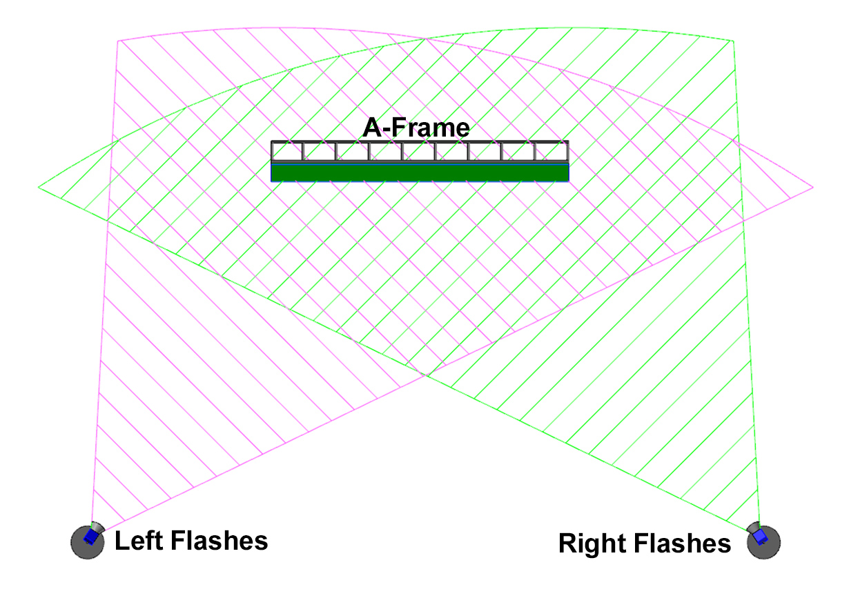
Flash Pointing Instructions
The flash units include a cone shaped reflector on the front of the flash. This reflector helps direct the light forward, and it helps keep the user from looking directly at the flash bulb.
The important thing about the reflector is that is does not block any of the light from any part of the A-frame.
Adjusting the lights left to right.
Stand behind the flash unit facing the A-frame. Look at the angle of the reflector on the flash. Be sure that the angle of the reflector completely covers the left and right sides of the A-frame. Do this for all 4 lights. See the diagram above.
Adjusting the lights up and down.
Stand to the side of the photostation and look at the angle of the reflector on the flash unit. The angle should go below and above the A-frame as viewed from the side. Do this for all 4 flash units.
Pointing the flashes