Support
Locating a slab on a saw
Locating a slab on a saw
There are numerous ways to locate a slab on your saw.
1- Using your saw’s camera/projection laser. If you have a saw that already uses a laser or camera to locate the slab on the saw, you can use the DXF layout from Slabsmith to align the outline of the slab with the slab on your saw.
2- Using Slabsmith’s “Locator software”. If you do not have a location camera/laser on your saw, you can mount a camera over your saw and use the locator module available from Slabsmith to align your DXF layout to the position of the slab on your saw. ( see here for more information on Locator )
2- Using location fixtures. If you are creating all of your own digital slabs, you can use matching fixtures to locate your slab on your saw. This is described in more detail below.
Using location fixtures
Using location fixtures is a valid and accurate way to locate your slab on your saw as long as you are creating all of your own digital slabs and not purchasing Slabsmith digital slabs from someone else. (for instance a slab manufacturer who creates Slabsmith digital slabs on their polishing line.)
The basic principle is to create matching ‘zero’ points between your Slabsmith photostation A-frame and your saw table.
Pre-requisites
If your saw table has slab rests on the edge of the table, you will need to fabricate your photostation A-frame to match the rest width and spacing.
If your saw table does not have rests on the edge, you will need to fabricate slab rests for the saw, and then build the A-frame to match.
We recommend using only 2 slab rests for these fixtures. Two rests makes it impossible to place a natural stone slab at an incorrect rotation. If you use a flat bottom to rest the slab on, or try and use 3 points of contact (ie- 2 on the bottom and one on the left side) it’s possible to place the slab against the fixtures in a rotated orientation without realizing it.
Implementation
If you have a single saw, you can simply change the zero point of your Slabsmith calibration to match your saw zero point. In effect you are making the A-frame have the same relationship from zero to the fixture as the distance from zero to the fixtures on your saw.
If you have a twin table machine or multiple saws, it becomes a little more complicated because each saw table must have the fixtures located the same distance from zero. (NOTE: From version 2017.5 and after, additional offsets can be added to the DXF export to individual tables to allow for differences between the 0,0 to rests. The rests still must be the same width and spacing, but the zero can be different.)
There are two ways to align the zero to fixture distance on multiple saw tables.
1- One is to very carefully place the fixtures the same distance from table zero on each saw.
2- The other is to place the fixtures in the best location on the saw table and then adjust the zero point of the saw in the saw’s control. In most cases you will need to work with the saw manufacturer to change the zero position of the table.
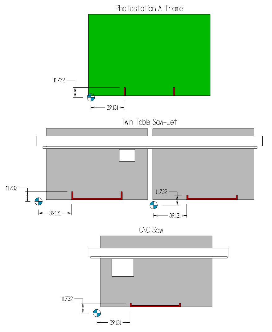
The image below show’s how the fixtures might look on the A-frame and multiple saws. In each example you will see that the distance between the zero point and the fixtures is identical.
Using the fixtures
In daily use the process works like this…
1- When you photograph the slab, mark the position were the fixtures touch the bottom of the slab with grease pencil.
2- Create a template in your programming software that matches the distance from zero to the fixtures. When everything is set up correctly, you will import the Slabsmith DXF layout and it will already be in the correct location for programming on your saws. Program the layout.
3- Place the slab on the saw so that the grease pencil marks you made when photographing are aligned with the fixtures on the saw.
4- Load the program and cut the slab.